Visual explainer
Robot Anatomy and Degrees of Freedom
Distinguish joint space from task space, calculate mobility with Grübler's formula, and map physical workspace limits.
A robot's degrees of freedom count the independent coordinates needed to specify its configuration. They do not guarantee independent motion in every task direction, or enough torque to hold every reachable load. Follow a planar arm with links 1.0 m and 0.8 m long; every numerical setting here is an illustrative fixture.
1. Two Descriptions, One Arm
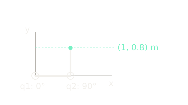
Joint coordinates describe the arm's internal pose: q1 is the first link angle from horizontal, and q2 is the second link angle relative to the first. At q1 = 0° and q2 = 90°, the elbow is at (1, 0) m and the tip is at (1, 0.8) m. The dashed projection locates that same tip in task coordinates. This page's task specifies tip position only; tip orientation is not a third independent control.
2. Links Meet At Joints
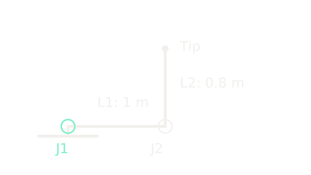
Rigid links keep their lengths; revolute joints permit relative rotation. This zoom changes from 120 to 200 drawing units per metre, preserving the 1:0.8 length ratio and the previous pose. The ground counts as a third link when counting mobility. Each ideal revolute joint supplies one relative angular coordinate, as described in Modern Robotics 2.2.
3. Count Independent Coordinates
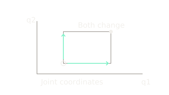
The plot is a local patch of joint space, not a map of hand positions. From the ring, change q1 alone, q2 alone, or both to reach different configurations. Two independent angles give two configuration degrees of freedom.
For this planar chain, Grübler's formula agrees: . N includes ground; J is the number of joints; each joint freedom is one. The count assumes independent constraints and is not a universal shortcut for every special mechanism.
4. Find The Workspace
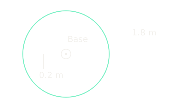
This top view uses 80 drawing units per metre and assumes unrestricted joint rotation, no self-collision and a position-only task. Full extension gives outer radius m; folding back gives inner radius m. Every radius between them is possible in this ideal model. The small circle is an unreachable hole, not a second workspace. Stops and obstacles can remove otherwise reachable positions.
5. Loads Create Joint Moments
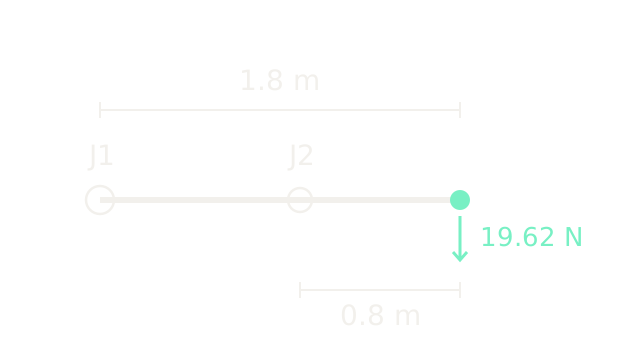
Return to 200 drawing units per metre and place both links horizontally. A 2.0 kg point payload exerts downward force N. Ignore link mass and motion to isolate payload statics. The horizontal lever arms are 1.8 m at J1 and 0.8 m at J2, so required holding torque magnitudes are 35.316 Nm and 15.696 Nm. The shoulder's demand is larger in this pose; that ordering is not universal across poses and link mass distributions. The general relationship is Jacobian-transpose statics, derived in Modern Robotics 5.2.
6. Pose Is Not Instantaneous Mobility
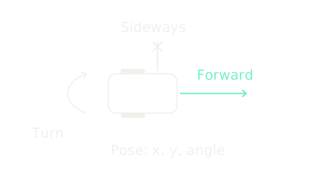
This separate top-down wheeled example needs three pose coordinates: x, y and heading. With rolling without lateral slip, its instantaneous body-sideways velocity is zero, though it can drive forward and turn. A sequence of turns and drives can reach a sideways-displaced pose. This is a nonholonomic velocity constraint, rather than a missing pose coordinate; see Modern Robotics 2.4. Arm joint freedom likewise does not promise every tip direction at a singularity.
7. Add A Redundant Joint
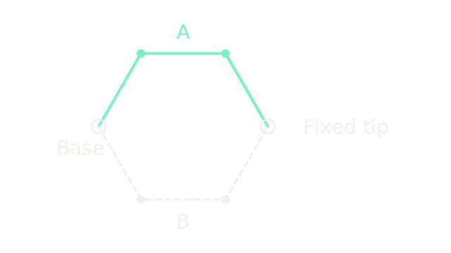
This explicitly changes to three links, each 1 m, drawn at 120 units per metre. The upper pose uses absolute link directions (60°, 0°, −60°); the dashed pose uses (−60°, 0°, 60°). Both end at m. Every drawn segment remains the same length.
Three joint coordinates for a two-coordinate position task generally leave one local self-motion direction where the position Jacobian has rank two. These two poses demonstrate different solutions, not a verified collision-free path between them. Tip orientation may change. Redundancy depends on the task; requiring orientation adds a constraint.
8. Respect Joint Stops
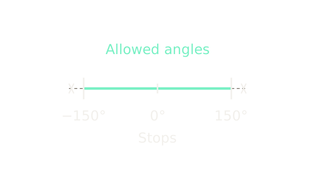
The ruler represents an example joint allowed from −150° to +150°. Bars mark the stops and crossed tails mark excluded angles. Mechanical interference, cables or software limits can impose bounds and shrink the ideal workspace. Some joints support continuous rotation, so bounded motion is not a universal property of robot joints.
9. Check Torque Feasibility
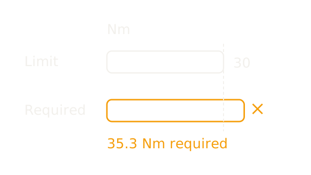
Return to the horizontal two-link arm and its 2 kg load. On a common torque scale, the required 35.316 Nm exceeds an assumed 30 Nm shoulder limit by 5.316 Nm. This simplified actuator cannot provide the calculated static balance. That does not establish a particular failure sequence: protection, brakes and mechanical support determine what actually happens. Link weight and dynamic loads would require additional modeling.
10. Where It Breaks
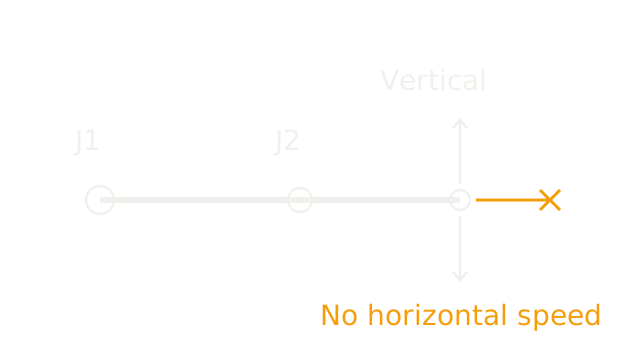
At q1 = q2 = 0°, the position Jacobian is:
Every finite joint-rate choice gives horizontal tip velocity zero; vertical velocity can be nonzero. The matrix has rank one instead of two. The arm still has two joint coordinates: singularity reduces the available instantaneous task motion. This distinction matches Modern Robotics 5.3.
Near a singularity, some requested tip velocities require very large joint rates; at the exact singularity an incompatible velocity has no finite joint-rate solution. This is not a universal claim of infinite acceleration. Finite repositioning inward may be possible after bending; the drawing describes first-order velocity at the straight pose.
The Quick Version
- Joint and task coordinates describe different aspects of one configuration.
- Rigid links preserve lengths while revolute joints permit relative rotation.
- Mobility counting assumes independent constraints.
- Unrestricted two-link reach lies between difference and sum of lengths.
- Payload torque depends on force and perpendicular lever arm.
- Three pose coordinates need not imply three independent instantaneous velocities.
- Redundancy depends on which task coordinates must stay fixed.
- Joint stops can remove part of the ideal workspace.
- Kinematic reach does not establish sufficient holding torque.
- Singularities remove task velocity directions without removing joint coordinates.